A Layout Editor turntable is a schematic representation of a turntable on the layout. A turntable is drawn as a circle with a variable number of track connections, called ray tracks. Each ray track is drawn as a short stub track radiating from the turntable circle. A track segment should connect to each ray track. Most of these track segments will connect a ray track to an end bumper. The distance of each ray track connection point from the turntable circle is fixed, but the direction of each ray track may be varied by dragging its connection point around the turntable circle. Any number of turntables may be added to a panel, and each turntable may have any number of ray tracks.
A turntable is added to a panel by selecting Add Turntable in the panel's Options ⇒ Add menu. New turntables are placed at the center of the panel, and should be moved to the desired location by dragging its center point with the meta key pressed (right button drag on Windows). A turntable can also be added to a panel by selecting the Turntable option in the toolbar and doing a shift-click at the desired location on the panel.
When a turntable is added, it has four ray tracks located in up, down, left, and right directions. The turntable's popup menu has two items. Selecting Edit… brings up an Edit Turntable dialog, and selecting Delete deletes the turntable. Before a turntable is actually deleted, the program asks for verification of that action.
 The Edit
Turntable dialog allows the following:
The Edit
Turntable dialog allows the following:
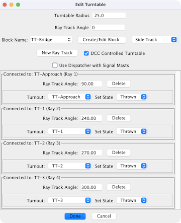
Ray track angles are measured from the vertical in a clockwise direction. So, thinking of an analog clock, an angle of 0 degrees is exactly vertical (the 12 o'clock position). Similarly an angle of 90 degrees corresponds to the 3 o'clock position, 180 degrees to 6 o'clock, 270 degrees to 9 o'clock, and so on. Angles are always entered in degrees.
To add a ray track, enter the angle corresponding to it's desired position in Ray Track Angle, and click New Ray Track. The turntable shows the new ray track immediately. To delete a ray track, find it in the connection list and press Delete. The ray track, and any connected track segment are immediately deleted from the panel. Caution: There is no undo for these operations.
Note: An easy procedure is possible for accurately aligning ray track connection points and end bumpers so that each track segment extends through the center of the turntable. After positioning the center of the turntable, and after adding ray tracks where needed, expand the radius of the turntable by a factor of three to four. Then add end bumpers adjacent to (or on top of) each ray track connection point. After shrinking the radius back to its final radius, add track segments. Track segments will be aligned fairly precisely to the turntable center.
since 5.15.1The bridge track can drawn as either Side Track or Mainline Track.
When this is selected it allows for control of turntables (and drivers) that use DCC turnout
addresses to set the turntable to various positions. Such examples are the LDT TT-DEC or
Heljan DCC Turntable. For each Ray, select the DCC turnout address and the position
required to set it.
To set the turntable to the desired position, simply click on the ray that you wish the
turntable to be aligned with.
Note: There is no support for selecting the Head or Tail of the turntable bridge.
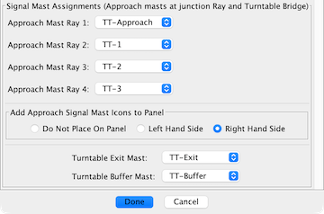
When the Use Dispatcher with Signal Masts option is enabled, the edit dialog is expanded.
While designed for use by Dispatcher, the signal masts can be used by any logic tool.
Each ray has an approach signal mast. The destination mast for the signal mast logic (SML) is a Buffer mast. When the turntable is aligned to the ray and the bridge is not occupied, the approach mast will display an aspect indicating it is safe to move onto the turntable bridge. The SML is not automatically created. Use Auto Generate Signaling Pairs to create the SML.
The move from the bridge to a ray track is controlled by the Exit mast. The Exit mast has SML for each ray track that contains a signal mast at the end bumper or at an anchor point. When the turntable is aligned to the ray and the ray is not occupied, the Exit mast will display an aspect indicating that is is safe to move from the bridge to the ray. The signal masts for the end bumpers or anchor points have to be manually attached using Set Signal Masts. After attaching the masts, use Auto Generate Signaling Pairs to create the SML.
The Buffer and Exit signal masts are not automatically added to the panel. For reference it is handy to manually add these to the panel.
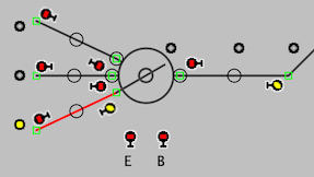
This is an example of a three ray turntable with a single layout connection.
The changes that implement Use Dispatcher with Signal Masts need to be removed when the option is disabled, a ray is deleted or the turntable is deleted. Removing the changes prevents JMRI errors and Java exceptions.
If a change is not allowed, a dialog will display a list of the items to be removed. This image shows the items to be removed before deleting a turntable ray.
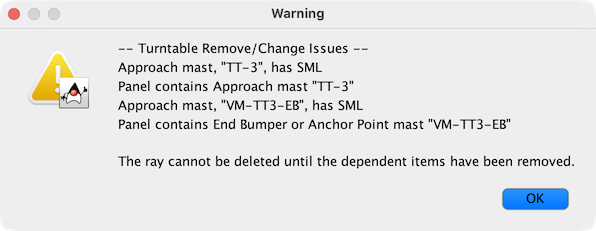
Use the Signal Mast Logic table to remove the SML items.